
|
| Brand Name: | KINGSINE |
| Model Number: | K3163i |
| MOQ: | 1 set |
| Delivery Time: | 15 working days |
| Payment Terms: | T/T in advance,L/C |
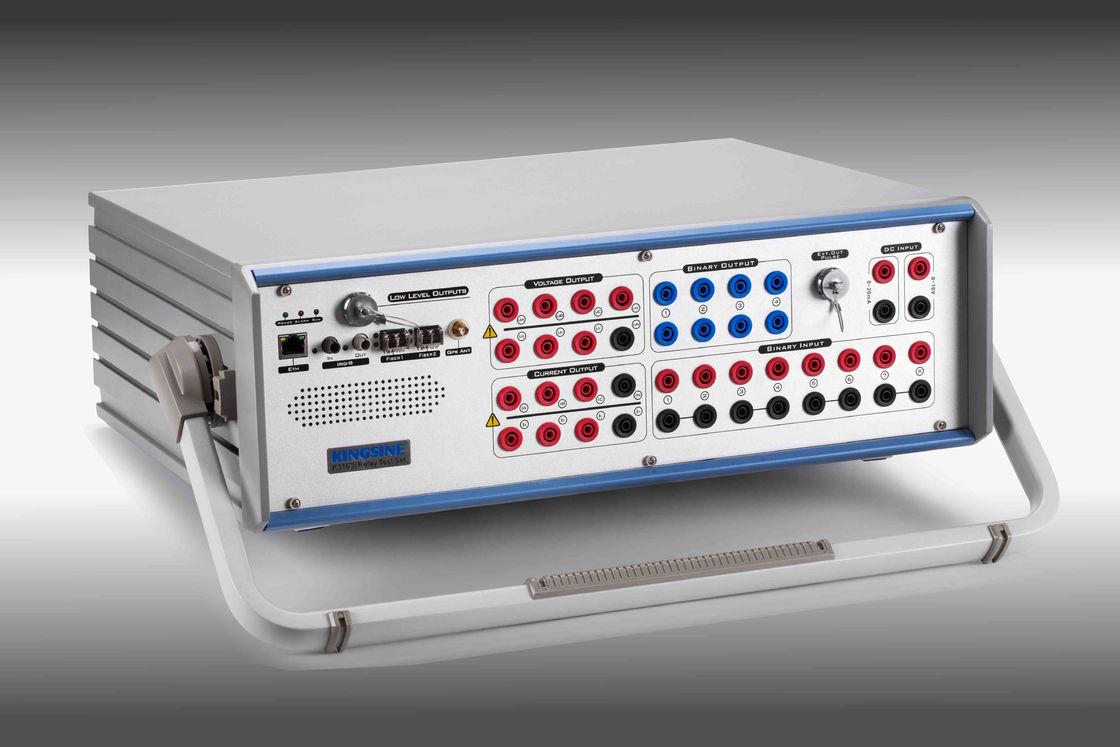
All-in-One design, Integrated IEC61850 SV & GOOSE, 6I+4V analog channels output, Inbuilt GPS and IRIG-B, and other advance functions.
Complied IEC61850-9-1, IEC61850-9-2, IEC60044-7/8, etc
100/1000Mbit Fiber port for SMV and GOOSE simulations
6x35A & 4x310V independent high burden output channels
13 channels independent low-level signal outputs
AC/DC measurement (8 channels inputs, 0.1 class, 0-600V/0-5A, auto range)
Transducer calibration (0.02 class)
Energy meter calibration (Mechanical & Electronic meters)
Transient play back up to 3KHz
Lightweight, <18Kg
Fully function KRT software testing modules
3-Years guarantee of free repair and life-long maintenance
Free software upgrade
Ordering Ref.
| Model | Current Outputs | Voltage Outputs |
| K3166 | 6×35A @ 450VA max / 3×70A @ 850VA max | 7×130V @ 75VA max |
| K3166i | 6×35A @ 450VA max / 3×70A @ 850VA max | 7×310V @ 90VA max |
| K3163 | 6×35A @ 450VA max / 3×70A @ 850VA max | 4×130V @ 75VA max |
| K3163i | 6×35A @ 450VA max / 3×70A @ 850VA max | 4×310V @ 124VA max |
| K3130 | 3×35A @ 450VA max | 4×130V @ 75VA max |
| K3130i | 3×35A @ 450VA max | 4×310V @ 124VA max |
Able of what K31 series can test
| Items | ANSI® No. |
| IEC61850 numerical IEDs relay & merge unit | |
| Distance protection relay | 21 |
| Synchronising or synchronism-check relays | 25 |
| Undervoltage relays | 27 |
| Directional Power relays | 32 |
| Undercurrent or underpower relays | 37 |
| Negative sequence overcurrent relays | 46 |
| Overcurrent/ground fault relays | 50 |
| Inverse time overcurrent/ground fault relays | 51 |
| Power factor relays | 55 |
| Overvoltage relays | 59 |
| Voltage or current balance relays | 60 |
| Directional overcurrent relays | 67 |
| Directional ground fault relays | 67N |
| DC overcurrent relays | 76 |
| Phase-angle measuring or out-of-step protection relays | 78 |
| Automatic reclosing devices | 79 |
| Frequency relays | 81 |
| Motor overload protection relays | 86 |
| Differential protection relays | 87 |
| Directional voltage relays | 91 |
| Voltage and power directional relays | 92 |
| Tripping relays | 94 |
| Voltage regulating relays | |
| Overimpedance relays, Z> | |
| Underimpedance relays, Z | |
| Time-delay relays |
Characteristics
Variable battery simulator, DC 0-350V, 140Watts max.
13 Low-level channels outputs up to 8Vac/10Vdc max.
0-600V / 0-5A AC/DC measurement in 0.1 class.
Graphical test modules and templates for testing of various relays
Quick relay testing facility in Manual mode
Shot/Search/Check, Point & Click testing
RIO/XRIO import & export facility
Switch on to fault test(SOTF)
Power system model for dynamic testing
Inbuilt GPS and IRIG-B sync end-to-end testing
Online Vector display
Automatic test results assume
Automatic test report creation
Anti-clipping detect, Wrong wiring connect alarm and self-protect, overload and overheat protection
Parameter
| Voltage Outputs | ||||
| Output Range & Power | 4×310 V ac (L-N) | 124 VA max each | ||
| 2×620 V ac (L-L) | 248 VA max each | |||
| 3×350 V dc (L-N) | 140 W max each | |||
| Accuracy |
AC: <0.03%Rd+0.01Rg Typ. <0.07%Rd+0.03Rg Guar. |
|||
|
DC: ±10mV @ <5V, ±0.5% @ ≥5V |
||||
| Resolution | 1mV | |||
| Distortion | <0.05%Typ. / <0.1% Guar. | |||
| Current Outputs | ||||
| Output Range & Power | 6×35A ac (L-N) | 450 VA max each | ||
| 3×70A ac (2L-N) | 850 VA max each | |||
| 1×100A ac (6L-N) | 1200 VA max | |||
| 3×20A dc (L-N) | 300W max each | |||
| Accuracy |
AC: <0.05%Rd+0.02Rg Typ. <0.15%Rd+0.05Rg Guar. |
|||
| DC: ±5mA @ <1A, ±0.5% @ ≥1A | ||||
| Resolution | 1mA | |||
| Distortion | <0.05%Typ. / <0.1% Guar. | |||
| 13 Low-Level Channel Outputs | ||||
| Quantity | 13 Channels, 16 pin aviation socket | |||
| Voltage Outputs Range | AC 0~8V, DC 0~10V | |||
| Current Outputs Range | Nominal 2mA, 10mA max transient | |||
| Output Power | ≥0.5VA | |||
| Accuracy |
(0.01~0.8 Vrms):<0.05% Typ. / <0.1% Guar. (0.8~8 Vrms): <0.02% Typ. / <0.05% Guar. |
|||
| Resolution | 0.25mV | |||
| Distortion(THD%) | <0.05% Typ. / <0.1% Guar. | |||
| Frequency & Phase Angle | ||||
| Frequency Range | DC~1KHz, 3KHz transient | |||
| Frequency Accuracy | ±1ppm | |||
| Frequency Resolution | 0.001 Hz | |||
| Phase Range | -360°~360° | |||
| Phase Accuracy | <0.05° Typ. / <0.1° Guar. 50/60Hz | |||
| Phase Resolution | 0.001° | |||
| IEC61850 Fiber & GOOSE Ethernet Ports (Optional Function) | ||||
| Fiber Ports |
2 x 100Base-FX Full Duplex, LC type (Optional to 10/100Mbit, Ethernet RJ45 type) |
|||
| Fiber Type | 62.5/125um (Multiple optical fiber, Orange Red) | |||
| Wavelength | 1310nm | |||
| Transmit Distance | >1Km | |||
| Indicator |
Spd Green(light): Valid connection Link/Act Yellow(Blinking): Data exchanging |
|||
| Note: | All hardware of this module are ready for active | |||
| Aux. DC Voltage Source (Battery simulator) | ||||
| Range | 0~350V @ 140W max | |||
| Accuracy | 0.5%Rg Guar. | |||
| Binary Input | ||||
| Quantity | 8pairs | |||
| Type | wet/dry, measurement | |||
| Threshold | 10~600Vdc or potential free, Programmable | |||
| Time resolution | 100us | |||
| Debounce time | 0~25ms (Software Controlled) | |||
| Time range | Infinite | |||
| Time errors | ±1ms @ 0.001~1s, ±0.1% @ >1s | |||
| Galvanic isolation | 4 isolated with each 2 pairs | |||
| Binary Output (Relay Type) | ||||
| Quantity | 4pairs | |||
| Type | Potential free relay contacts, software controlled | |||
| Break Capacity AC | Vmax: 400Vac / Imax:8A / Pmax:2500VA | |||
| Break Capacity DC | Vmax: 300Vdc / Imax:5A / Pmax:150W | |||
| Binary Output (Semiconductor Type) | ||||
| Quantity | 4pairs | |||
| Type: | Open-collector, 14 pin Aviation socket | |||
| Break Capacity DC |
5~15Vdc / 5mA, 10mA max AC not permit |
|||
| Response time: | 100us | |||
| Synchronization | ||||
| Synchronization Mode |
GPS, SMA type antenna connector IRIG-B, FT3 IEEE1588 |
|||
| Power supply & Environment | ||||
| Nominal Input Voltage | 100~240Vac | |||
| Permissible Input Voltage | 85~264Vac, 125~350VDC | |||
| Nominal Frequency | 50/60Hz | |||
| Permissible Frequency | 45Hz~65Hz | |||
| Power Consumption | 1500 VA max | |||
| Connection Type | Standard AC socket 60320 | |||
| Operating Temperature | -10℃~55℃ | |||
| Storage Temperature | -20℃~70℃ | |||
| Humidity | <95%RH, non-condensing | |||
| Others | ||||
| PC Connection | RJ45 Ethernet, 10/100/1000M | |||
| Grounding Terminal | 4mm banana socket | |||
| Weight | 18 Kg | |||
| Dimensions(W x D x H) | 468×375×164(mm) | |||
Additional Information (Optional Modules)
| DC Measurement Input (Transducer calibrator) | |||
| Voltage Input | Range | 0~±10V dc | |
| Max Input | ±11V dc | ||
| Accuracy | <0.02% rg Typ. <0.05% rg Guar. | ||
| Input Impedance | 1Mohm | ||
| Current Input | Range | 0~±1mA / 1~±20mA, auto range | |
| Max Input | 600mA | ||
| Accuracy | <0.02% rg Typ. <0.05% rg Guar. | ||
| Input Impedance | 15 ohm | ||
| AC/DC Measurement Input (Standard meter) | |||
| Input Quantity | 8 inputs (blend with binary input pairs) | ||
| Voltage range | 0~600Vrms (Rg:0.1V,1V, 10V, 60V, 600V) | ||
| Voltage accuracy | <0.1% Rg | ||
| Current range | 0~5Arms(clamp input) | ||
| Current accuracy | <0.1% Rg | ||
| Sample rate | 10KHz | ||
| Input impedance | 600KΩ | ||
| Frequency range | 45~65Hz, Accuracy < 0.01Hz | ||
| Phase accuracy | 0~360°, <0.2° Typ. | ||
| Energy Meter Calibration | |||
| Sensor Usage | Mechanical meters / Electronic meters | ||
| Sensor Output | High lever:>4.5V, Low level:<0.2V | ||
| Pulse Input | 1 pulse input port | ||
| Pulse Range | 500KHz pulse input Max. | ||
| Pulse Output |
1 Transistor output, Open-collector, 5-15Vdc/5mA |
||
|
|

| Brand Name: | KINGSINE |
| Model Number: | K3163i |
| MOQ: | 1 set |
| Payment Terms: | T/T in advance,L/C |
All-in-One design, Integrated IEC61850 SV & GOOSE, 6I+4V analog channels output, Inbuilt GPS and IRIG-B, and other advance functions.
Complied IEC61850-9-1, IEC61850-9-2, IEC60044-7/8, etc
100/1000Mbit Fiber port for SMV and GOOSE simulations
6x35A & 4x310V independent high burden output channels
13 channels independent low-level signal outputs
AC/DC measurement (8 channels inputs, 0.1 class, 0-600V/0-5A, auto range)
Transducer calibration (0.02 class)
Energy meter calibration (Mechanical & Electronic meters)
Transient play back up to 3KHz
Lightweight, <18Kg
Fully function KRT software testing modules
3-Years guarantee of free repair and life-long maintenance
Free software upgrade
Ordering Ref.
| Model | Current Outputs | Voltage Outputs |
| K3166 | 6×35A @ 450VA max / 3×70A @ 850VA max | 7×130V @ 75VA max |
| K3166i | 6×35A @ 450VA max / 3×70A @ 850VA max | 7×310V @ 90VA max |
| K3163 | 6×35A @ 450VA max / 3×70A @ 850VA max | 4×130V @ 75VA max |
| K3163i | 6×35A @ 450VA max / 3×70A @ 850VA max | 4×310V @ 124VA max |
| K3130 | 3×35A @ 450VA max | 4×130V @ 75VA max |
| K3130i | 3×35A @ 450VA max | 4×310V @ 124VA max |
Able of what K31 series can test
| Items | ANSI® No. |
| IEC61850 numerical IEDs relay & merge unit | |
| Distance protection relay | 21 |
| Synchronising or synchronism-check relays | 25 |
| Undervoltage relays | 27 |
| Directional Power relays | 32 |
| Undercurrent or underpower relays | 37 |
| Negative sequence overcurrent relays | 46 |
| Overcurrent/ground fault relays | 50 |
| Inverse time overcurrent/ground fault relays | 51 |
| Power factor relays | 55 |
| Overvoltage relays | 59 |
| Voltage or current balance relays | 60 |
| Directional overcurrent relays | 67 |
| Directional ground fault relays | 67N |
| DC overcurrent relays | 76 |
| Phase-angle measuring or out-of-step protection relays | 78 |
| Automatic reclosing devices | 79 |
| Frequency relays | 81 |
| Motor overload protection relays | 86 |
| Differential protection relays | 87 |
| Directional voltage relays | 91 |
| Voltage and power directional relays | 92 |
| Tripping relays | 94 |
| Voltage regulating relays | |
| Overimpedance relays, Z> | |
| Underimpedance relays, Z | |
| Time-delay relays |
Characteristics
Variable battery simulator, DC 0-350V, 140Watts max.
13 Low-level channels outputs up to 8Vac/10Vdc max.
0-600V / 0-5A AC/DC measurement in 0.1 class.
Graphical test modules and templates for testing of various relays
Quick relay testing facility in Manual mode
Shot/Search/Check, Point & Click testing
RIO/XRIO import & export facility
Switch on to fault test(SOTF)
Power system model for dynamic testing
Inbuilt GPS and IRIG-B sync end-to-end testing
Online Vector display
Automatic test results assume
Automatic test report creation
Anti-clipping detect, Wrong wiring connect alarm and self-protect, overload and overheat protection
Parameter
| Voltage Outputs | ||||
| Output Range & Power | 4×310 V ac (L-N) | 124 VA max each | ||
| 2×620 V ac (L-L) | 248 VA max each | |||
| 3×350 V dc (L-N) | 140 W max each | |||
| Accuracy |
AC: <0.03%Rd+0.01Rg Typ. <0.07%Rd+0.03Rg Guar. |
|||
|
DC: ±10mV @ <5V, ±0.5% @ ≥5V |
||||
| Resolution | 1mV | |||
| Distortion | <0.05%Typ. / <0.1% Guar. | |||
| Current Outputs | ||||
| Output Range & Power | 6×35A ac (L-N) | 450 VA max each | ||
| 3×70A ac (2L-N) | 850 VA max each | |||
| 1×100A ac (6L-N) | 1200 VA max | |||
| 3×20A dc (L-N) | 300W max each | |||
| Accuracy |
AC: <0.05%Rd+0.02Rg Typ. <0.15%Rd+0.05Rg Guar. |
|||
| DC: ±5mA @ <1A, ±0.5% @ ≥1A | ||||
| Resolution | 1mA | |||
| Distortion | <0.05%Typ. / <0.1% Guar. | |||
| 13 Low-Level Channel Outputs | ||||
| Quantity | 13 Channels, 16 pin aviation socket | |||
| Voltage Outputs Range | AC 0~8V, DC 0~10V | |||
| Current Outputs Range | Nominal 2mA, 10mA max transient | |||
| Output Power | ≥0.5VA | |||
| Accuracy |
(0.01~0.8 Vrms):<0.05% Typ. / <0.1% Guar. (0.8~8 Vrms): <0.02% Typ. / <0.05% Guar. |
|||
| Resolution | 0.25mV | |||
| Distortion(THD%) | <0.05% Typ. / <0.1% Guar. | |||
| Frequency & Phase Angle | ||||
| Frequency Range | DC~1KHz, 3KHz transient | |||
| Frequency Accuracy | ±1ppm | |||
| Frequency Resolution | 0.001 Hz | |||
| Phase Range | -360°~360° | |||
| Phase Accuracy | <0.05° Typ. / <0.1° Guar. 50/60Hz | |||
| Phase Resolution | 0.001° | |||
| IEC61850 Fiber & GOOSE Ethernet Ports (Optional Function) | ||||
| Fiber Ports |
2 x 100Base-FX Full Duplex, LC type (Optional to 10/100Mbit, Ethernet RJ45 type) |
|||
| Fiber Type | 62.5/125um (Multiple optical fiber, Orange Red) | |||
| Wavelength | 1310nm | |||
| Transmit Distance | >1Km | |||
| Indicator |
Spd Green(light): Valid connection Link/Act Yellow(Blinking): Data exchanging |
|||
| Note: | All hardware of this module are ready for active | |||
| Aux. DC Voltage Source (Battery simulator) | ||||
| Range | 0~350V @ 140W max | |||
| Accuracy | 0.5%Rg Guar. | |||
| Binary Input | ||||
| Quantity | 8pairs | |||
| Type | wet/dry, measurement | |||
| Threshold | 10~600Vdc or potential free, Programmable | |||
| Time resolution | 100us | |||
| Debounce time | 0~25ms (Software Controlled) | |||
| Time range | Infinite | |||
| Time errors | ±1ms @ 0.001~1s, ±0.1% @ >1s | |||
| Galvanic isolation | 4 isolated with each 2 pairs | |||
| Binary Output (Relay Type) | ||||
| Quantity | 4pairs | |||
| Type | Potential free relay contacts, software controlled | |||
| Break Capacity AC | Vmax: 400Vac / Imax:8A / Pmax:2500VA | |||
| Break Capacity DC | Vmax: 300Vdc / Imax:5A / Pmax:150W | |||
| Binary Output (Semiconductor Type) | ||||
| Quantity | 4pairs | |||
| Type: | Open-collector, 14 pin Aviation socket | |||
| Break Capacity DC |
5~15Vdc / 5mA, 10mA max AC not permit |
|||
| Response time: | 100us | |||
| Synchronization | ||||
| Synchronization Mode |
GPS, SMA type antenna connector IRIG-B, FT3 IEEE1588 |
|||
| Power supply & Environment | ||||
| Nominal Input Voltage | 100~240Vac | |||
| Permissible Input Voltage | 85~264Vac, 125~350VDC | |||
| Nominal Frequency | 50/60Hz | |||
| Permissible Frequency | 45Hz~65Hz | |||
| Power Consumption | 1500 VA max | |||
| Connection Type | Standard AC socket 60320 | |||
| Operating Temperature | -10℃~55℃ | |||
| Storage Temperature | -20℃~70℃ | |||
| Humidity | <95%RH, non-condensing | |||
| Others | ||||
| PC Connection | RJ45 Ethernet, 10/100/1000M | |||
| Grounding Terminal | 4mm banana socket | |||
| Weight | 18 Kg | |||
| Dimensions(W x D x H) | 468×375×164(mm) | |||
Additional Information (Optional Modules)
| DC Measurement Input (Transducer calibrator) | |||
| Voltage Input | Range | 0~±10V dc | |
| Max Input | ±11V dc | ||
| Accuracy | <0.02% rg Typ. <0.05% rg Guar. | ||
| Input Impedance | 1Mohm | ||
| Current Input | Range | 0~±1mA / 1~±20mA, auto range | |
| Max Input | 600mA | ||
| Accuracy | <0.02% rg Typ. <0.05% rg Guar. | ||
| Input Impedance | 15 ohm | ||
| AC/DC Measurement Input (Standard meter) | |||
| Input Quantity | 8 inputs (blend with binary input pairs) | ||
| Voltage range | 0~600Vrms (Rg:0.1V,1V, 10V, 60V, 600V) | ||
| Voltage accuracy | <0.1% Rg | ||
| Current range | 0~5Arms(clamp input) | ||
| Current accuracy | <0.1% Rg | ||
| Sample rate | 10KHz | ||
| Input impedance | 600KΩ | ||
| Frequency range | 45~65Hz, Accuracy < 0.01Hz | ||
| Phase accuracy | 0~360°, <0.2° Typ. | ||
| Energy Meter Calibration | |||
| Sensor Usage | Mechanical meters / Electronic meters | ||
| Sensor Output | High lever:>4.5V, Low level:<0.2V | ||
| Pulse Input | 1 pulse input port | ||
| Pulse Range | 500KHz pulse input Max. | ||
| Pulse Output |
1 Transistor output, Open-collector, 5-15Vdc/5mA |
||

